Analysis
a. Approach: Proposed Solution
The conception of this design comes from the need for a structure that is both light in weight as well as strong in tension and compression. This project was chosen because it applies concepts that are relevant to senior class learning such as MET 418. In order to better distribute a load across all members cross sectional beams have been added to redistribute the load while not adding to the overall weight so that it surpasses the weight limit specified in the requirements section of this proposal.
b. Design Description
The design is based around redistribution of loads in order to properly mitigate all of the load being placed on one portion of the bridge. This will help to reduce forces in one direction and allow for other members to reduce loading on other members. While benchmarks that can be found don’t match this project exactly it gives a good idea of what to expect while designing a bridge. Balsabridge.com has many examples of award-winning bridges that can be used to compare designs. The rules for that competition are different from the requirements in this project but it appears that many of the designs are similar to the type of design used in this analysis. The use of triangular shapes seems to be a reoccurring theme which this design follows in order to create strength between members. What this design improves upon is the ability to articulate in the vertical direction allowing for a secondary level of depth within the project creating an even greater engineering challenge.
c. Benchmark
There are many similar projects to this one as balsa wood bridges have been a great way to show engineering knowledge for years now. This means that there are many benchmarks that this project can be compared and analyzed against.
d. Performance Predictions
The performance prediction for this project is centered around how much weight the bridge will be able to hold when it comes to testing. The prediction being placed is 30kg as this is what the design is being evaluated for once the design factor of safety of 1.5 has been added. This factor of safety should allow for a comfort zone in which the bridge will meet the minimum requirements while still maintaining a low weight of the structure.
e. Description of Analysis
The first step in analysis of a bridge is to determine the forces acting on the structure as well as the location these forces will be acting in order to determine what reactionary forces will be required in ordered to sufficiently keep the bridge in static equilibrium. This analysis can be view in appendix A, green sheet A-1. This is the very first step that begins the lengthy process that is to come in order to properly assess the bridges ability to withstand the forces acting on the structure. These reactionary forces on each end of the bridge allow for the analysis of the bridge at each joint location as well as the ability to determine if each member is in tension or compression. Because the bridge is a mirror image of itself, calculating one side of the bridge also gives a clear picture as to what is happening on the other side of the structure as well which is detailed in appendix A, green sheets A-2 and A-3.
f. Scope of Testing and Evaluation
The scope of testing and evaluation is to determine if the bridge meets the standards set in the requirements previously listed above in the requirements section of the proposal. The testing will be used to determine if the project can be ruled a success or a failure based upon the success criteria previously established.
Requirements
For this Project a bridge is to be designed to meet specific requirements. These requirements are as follows.
will support at minimum between 18.9-20kg of mass.
This bridge must be within the specific dimensions as listed,
overall length must be at minimum 400mm long
House a 38mm wide road deck that extends the entire length of the bridge with no openings except for an 8mm wide hole for loading
The road deck must also be within 12mm of the abutment level either at the outside edge of the abutment or the ends of the bridge (whichever is closer)
The road deck may either be flat or have a smooth curve, if the deck is curved the difference between the low point and high point may not exceed 25mm
The bridge must allow passage of a rectangular object that is 32mm wide by 25mm in height.
the bridge also must be able to articulate in the vertical direction such that 50% of the overall length of the bridge is raised a minimum of 200mm.
While at rest the bridge should rest evenly on both abutments so that there is no gap between the bridge and the abutments on both sides.
Applying 10g of force to the lifting mechanism should allow for a 20lb piece of paper to slip between the abutment and the bridge at minimum.
i. Analysis 1
This was the first analysis of the bridge structure design. The required load for success is 20kg roughly 200N of force. The reactions at points A and B are crucial to determining the rest of the loads on each individual member of the bridge. Leading to the bigger picture once all forces are determined for every point it will allow for analysis of stresses and ultimately determining the thickness of each member of the bridge. This analysis brought forth the ability to determine what forces the bridge must be able to support without failure leading to a design parameter of how much force the bridge is required to hold. These calculations are detailed in appendix A, green sheet A-1.
ii. Analysis 2
This analysis was to determine how forces are distributed among each member as well at how joints will be loaded. This analysis brought forth the ability to accurately determine forces across each member which in turn will allow for a more detailed stress analysis and lend the ability to ultimately determine material thickness requirements in each member by assessing failure points. The design parameter achieved from this analysis is exactly that, it is the parameter of how much load each member is required to hold in order to not fail before meeting the minimum failure load. These calculations can be found in appendix A, green sheet A-2 and A-3. Because this bridge is a mirror image of itself by knowing the forces exerted on one side of the bridge you also can determine the other side of the bridge.
iii. Analysis 3
Analysis 3 is shown in appendix A-4. This calculation was a straightforward calculation of determining the overall length of each individual member associated with the bridge structure. This calculation was essential as it met the dimensional requirements set forth in the requirements section of the proposal. The bridge has met the length requirement of greater than 400mm as well as meeting the height requirement of 25mm.
iv. Analysis 4
Analysis 4 is documented in Appendix A-5. This calculation was the start of the more crucial calculations that will determine the amount of weight the bridge structure will be able to support without failure. Calculations for the lower beam dimensions are shown to be ½” x ¾” in order to support the required load with a design factor of 1.5. this meets the requirement of being able to support 20kg without failure.
v. Analysis 5
This analysis is documented in Appendix A-6. In order to determine the dimensions for the internal members of the bridge stress analysis was required in order to accurately determine the cross-sectional area and dimensions of the edge lengths. By using the stress equations shown in appendix A-6 it was determined that a piece of balsa wood ¼” x ¼” was required in order to properly support the required forces placed on the internal members.
vi. Analysis 6
The calculations described here can be viewed in Appendix A-7. One of the requirements of this bridge was that the overall mass of the structure would be no more than 85g in mass. This calculation detailed in appendix A-7 was a complete calculation of the overall mass of the bridge using the density of balsa wood and the volume of the individual members. this calculation showed that the overall mass was 10g below the requirement listed in the proposal above.
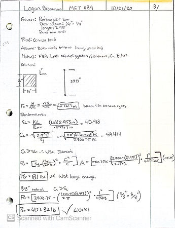
vii. Analysis 7
This calculation was the final strength analysis of the bridge in order to determine what sized columns would be needed in order to support the members that will be under compression. This was also a calculation that was used to determine if the bridge would meet the requirement of holding 20kg at minimum. These calculations can be found in appendix A-8.
viii. Analysis 8
The bridge has a requirement that says it must be able to articulate at least 50% of the bridge to a height of 280mm. The first step in order to meet this requirement is to determine how much force would be required to lift the bridge from a resting position. This information will allow for the calculation of what kind of mechanism should be used in order to properly raise the bridge to the required height.
viiii. Analysis 9
The bridge requirements states that the bridge must be able to articulate 280mm. The design that was decided on for this articulation was to have a tower of one side of the bridge with a small crank and a set of pulleys in order to wind up a string and pull the opposite end of the bridge up. This calculation shows how much string will be required in order to complete this operation. See appendix A-10
X. Analysis 10
The articulation design that was chosen for this bridge is one that requires a string at some angle to pull in the x direction as well as the Y this means that the tension in the string is going to be higher than the force that is actually required to lift the bridge. This calculation shows the amount of tension that will be within the string at any given time while moving the bridge up or down. See appendix A-11
Xi. Analysis 11
This analysis was done in order to determine the angle to which the bridge would sit when fully raised to the required height. This allowed for a better understanding of how the bridge would interact with the tower used to control the articulation components such as the pulley and the axle. This was an analysis that would lead to the final analysis 12. The calculations for this analysis can be found in appendix A-12.
Xii. Analysis 12
Once the bridge is in its fully retracted state the bridge will be under different loading as the angle changes relative to the top of the tower. This means that more force will be required to pull the bridge up than the force required to hold it up according to the calculations which will allow for an easier time sustaining the upright position. This analysis can be found in appendix A13.
Device: Parts, Shapes, and Conformation
. The justification for the design of the bridge is based on an attempted to take a center point load placed on the bridge and attempt to spread the forces evenly across all members without placing to much stress at any one location. The loads can be found in appendix A, green sheet A-2 and A-3. (more justification to come once more calculations have been done to determine stresses in locations)
Device Assembly
The device assembly addresses the problem at hand by taking individual components that alone would not be able to support the minimum 20kg weight and assembling them in a way which allows for a much larger forced to be applied on the structure. This includes adding reinforced joint plates to reduce likelihood of breakages on glued joints, using stress analysis to determine the required material cross-section at any given member and properly allowing materials to bond.
Technical Risk Analysis
With any project there is always some degree of technical risk associated with the project at hand. In the case of this project the technical risks could involve things such as the articulating portion of the bridge not properly operating to the design requirements such that it is not able to raise the bridge to a satisfactory height in which case that entire assembly would have to be replaces and redesigned causing a lot of time and project resource to be lost. There is also technical risk associated with the bridge itself. If during analysis the bridge structure is calculated to hold the required weight but in doing so the bridge exceeds the allowable weight limit for the structure an almost full redesign would be required.
Failure Mode Analysis
While preforming a failure mode analysis on the bridge the intent is to analyze as many aspects of the bridge as possible in order to paint a full picture of what type of loads, stresses, and strains will be placed on it in order to properly identify what material thickness and lengths will be required in order to meet design specifications. In particular bending stress, shear stress, normal stress, and moments in the material will play a big factor in determining where components are most likely to fail. This analysis will improve the reliability of the structure by reinforcing points that are most likely to fail.
Operation Limits and Safety
As with any type of devices that has large loads placed upon it P.P.E. should always be worn while in the area of the device. While constructing the bridge always use precaution while cutting any materials and have all guards in place. Also, where actuation occurs for the moving components of the bridge have a potential to pinch fingers or entangle hair so the structure should not be touched while under load. During testing splintering may occur which requires safety glasses to be worn at all times.
Forces on Bridge Ends

Column Buckling Force